In a production environment, you would want to separate the hypervisor and storage network to different networks/switches (just for easier management), but in our setup we will use one switch with multiple VLANs to isolate the traffic. This is more a function of cash flow for me as managed switches are usually several hundred dollars to start, as opposed to generic switches you can get for less than a c-note. Plus, a single switch can be an ok setup for a small biz (provided of course there is at least a cold spare, or even better a warm spare (switch with same config as production switch but not plugged) ).
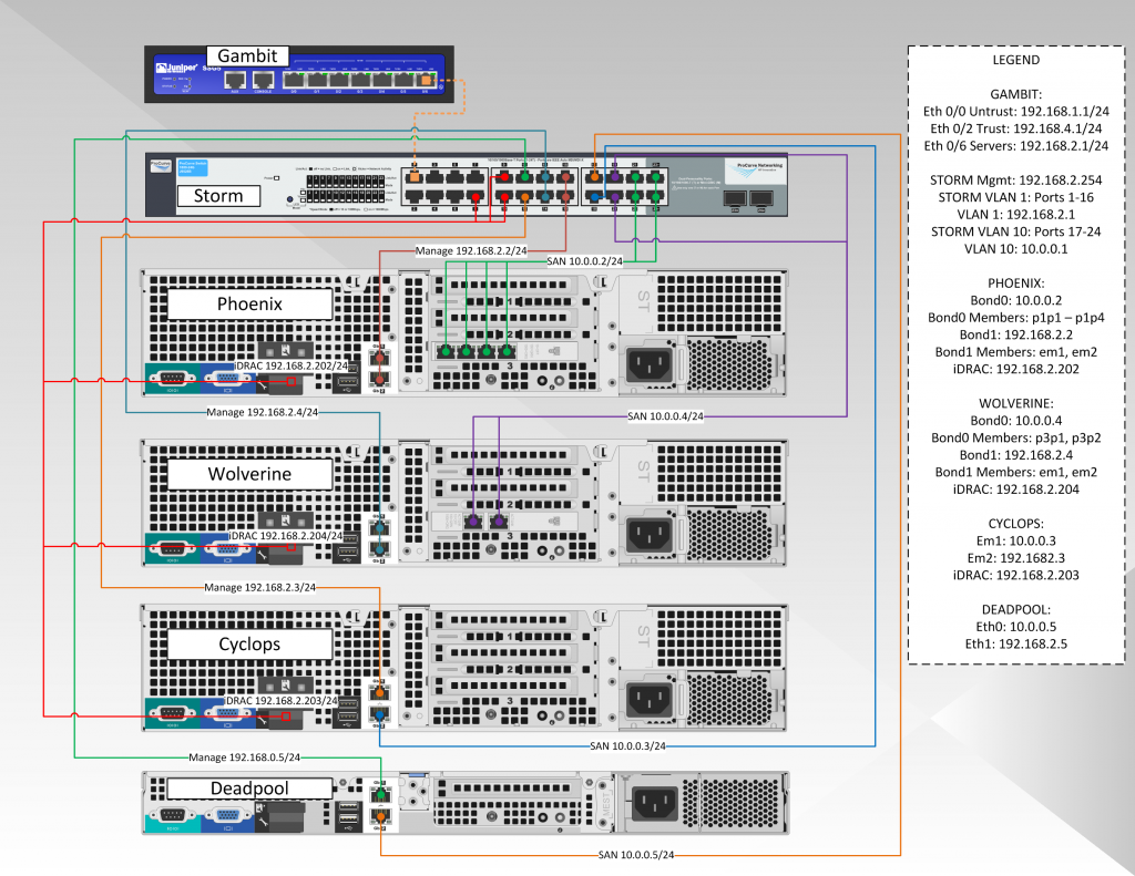
The diagram below shows our hypervisor production network:
Formally, you could make the argument to separate the Lights Out network to another VLAN, but in our case we will keep them on the production LAN. The reason you would want this VLAN separate is that if hacker were to get in, s/he would have the capability of shutting down the server, as the Lights Out (or iDrac as Dell calls it) has the capability of making BIOS changes or doing a hard reboot regardless of the OS on the system. In our setup we would need to either create a new VLAN and physically connect it to an interface on the SSG5, or we would need to tag port 1 of the HP switch to include all the VLANs the SSG would need access to (and likewise create the same tags on the SSG). VLAN tagging is what you want to use when you want to send multiple subnet traffic across one ethernet port (usually between switches or routers).
The most important switch configuration options we will be setting up are:
- Configure and IP address and password on the HP 1800-24G switch
- Create three separate VLANs (in our case VLAN 1 (Management), VLAN 5 (Lights Out), and VLAN 10 (Storage); in reality you could use any numbers you want)
- Configure LACP groups (this is so you can use multiple ports to be treated as a single interface, to be used with ethernet bonding)
- Assign the proper switch ports to the proper VLANs for individual NIC devices
- Assign the proper switch ports to the proper VLANs for the bonded NICs and LACP groups
- Enable SNMP for Cacti/Nagios to monitor
Configure the HP 1800-24G Management IP and Password
To configure the switch for a newly minted (or recently reset) HP switch, plug in a device that is on the 192.168.2.X subnet, and then open a web browser to 192.168.2.10 (this is the default IP for this particular device; check the notes for your specific switch). The default password is blank. The interface will look like below:
Pretty straightforward above, just enter the information for the Name, IP Address, and Password. No need for Rate Limits now.
Create Separate VLANs
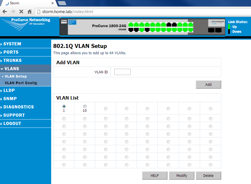
For our purposes we will create 3 VLANs: VLAN 1 for Management, VLAN 5 for Lights Out, and VLAN 10 for storage. for convention, I usually use the VLAN tag with the subnet it lines up with (e.g. VLAN 10 is 10.0.0.0/24, VLAN 2 is 192.168.2.0/24, VLAN 5 is 192.168.5.1). This is simple enough to do, as the VLANs are just numbers (tags or tag IDs, more accurately). Since the switch I have is a layer-2 device, I can only create tags and route tagged VLANs into and out of the switch. I cannot create an actual routing interface (which would require a layer-3 switch). So for us, we’ll goto the VLAN Setup menu item on the switch, and create VLANs 1 (default), 5 (LightsOut), and 10 (Storage). Pics below:
Next we will assign individual ports to the VLANs by selecting the VLAN, and then hitting the Modify button:
You’ll notice the two LAG groups in there. We’ll touch on those in a moment. But the above is linking the ports we would like for the first VLAN. Similarly, add ports to VLAN 5 and VLAN 10.
Create LACP/LAG Groups
A LAG or LACP group is a Link Aggregated Group (which just means more than one port treated as one port). This is useful for linking switches together (so if one port fails on either switch, the connection will still work through the remaining ports on the LAG). We have a couple LAG groups to create (the 4 port Storage LAG on Phoenix (which stores the NFS and iSCSI shares), the 2 ports on Phoenix that is the management share, the two ports on Wolverine that is the management network, and the other two ports on Wolverine that are the storage network). Cyclops and Deadpool have a single NIC each for management and storage, so they do not need LAGs.
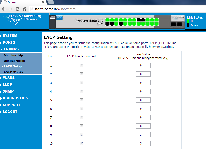
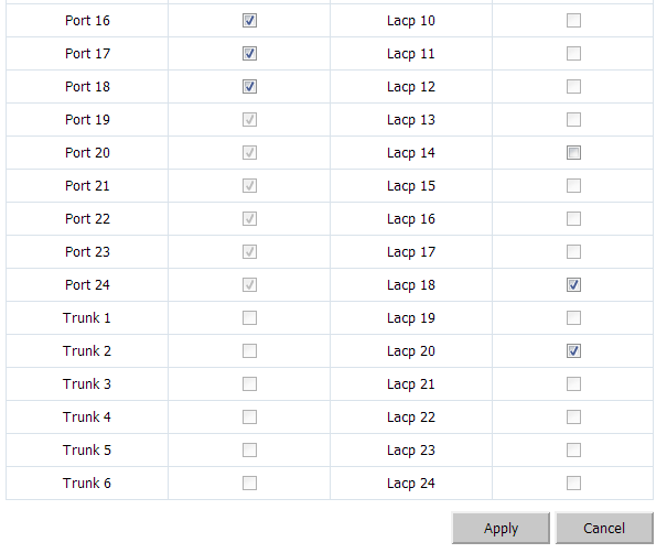
To create a LAG group, goto Trunks ~> LACP Setup and simply check the “LACP Enabled on Port” checkbox for the groups you would like to use, and make sure the key value matches for that set, as below:
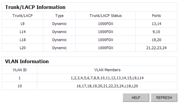
You can only see the top 10 ports above, but I also created a couple LACP groups below. Once you create the LAG groups, and assign the matching key, you can goto the LACP Status and check that they LAG groups are up (and you will also see their key ID assigned from the switch). Interestingly, the switch does not tell you the “Main” port of the LAG group here (the main port is the port that represents the LAG). To determine that, you have to click on the switch status link, in System ~> Information, as below:
In this setup, L9 represents the LAG group that includes ports 13,14 (Phoenix Management), L14 includes ports 9 and 10 (Wolverine Management), L18 includes ports 19 and 20 (Wolverine Storage), and L20 includes the four last ports of the switch (Phoenix Storage). When assigning VLANs, you would assign L-Port to the VLAN, which assigns the LAG to the VLAN (e.g. assigning L20 to VLAN 10 will make ports 21-24 all part of VLAN 10).
Assign Ports to Proper VLANs (including LAGs)
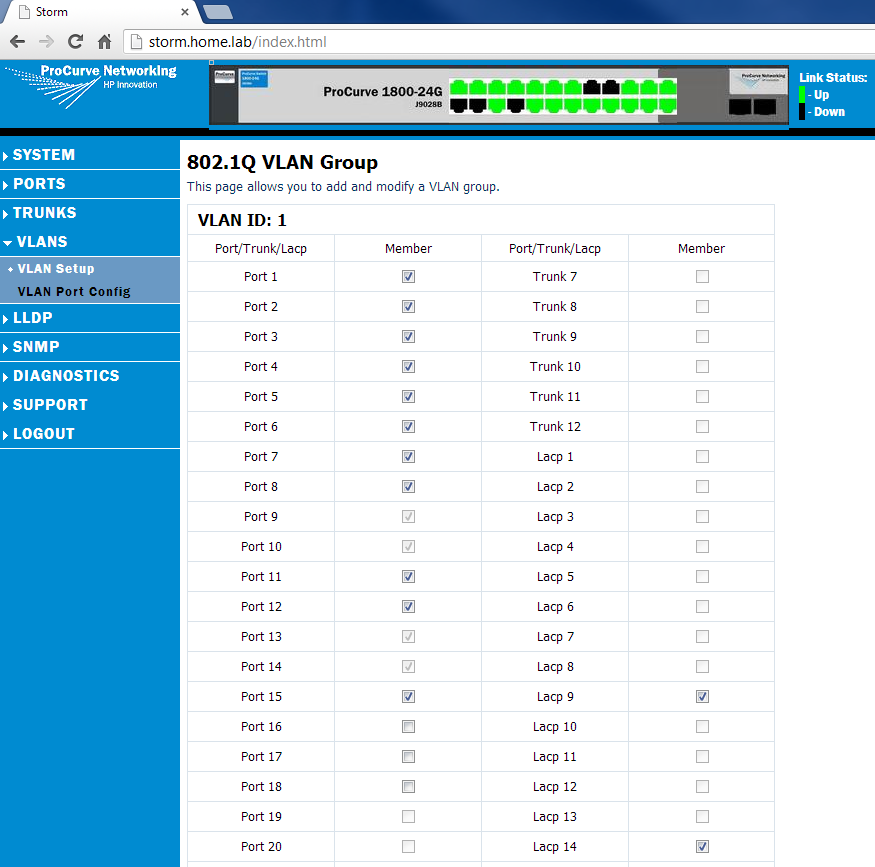
When clicking on the VLAN Setup link under VLANS, you will see a an option under VLAN List that shows the VLANs we have created (in our case, that is VLAN1 (Management), VLAN5 (LightsOut), and VLAN10 (Storage)). We will click on VLAN1 and make sure all the ports for the management side of the devices will be included (e.g. the Hypervisors 192.168 subnet, the firewall’s Trust subnet, Phoenix’s management port, etc):
I like to segregate my switch visually, so you can see network segments in chunks. The first 15 ports will be VLAN1, the next 4 will be Lights Out, and the final ones will be storage. In the above example, I assigned the first 15 ports to VLAN1. You’ll notice that ports 9-10 and 13-14 are greyed out. That is because they are part of LACP group 9 and LACP group 14. When we assign those LAG groups to VLAN1, the ports will follow (they are greyed out as the switch does not see them as individual ports once you make them a LAG group – it treats the LAG group as one virtual port, with two members, in the above case).
Similarly, we will add the proper ports for VLAN 10. As above, LACP groups 18 and 20 comprise the last 6 physical ports:
There are several LACP modes (or algorithms) that can be used how to load balance the traffic. That is outside the scope of this page (but will be tackled in another post). The positive news is that even if you cannot afford a managed switch, you there are built-in modes in Linux that will let you setup LACP-like behavior even with an unmanaged switch. The biggest benefit of a managed switch is that both devices parlez-vous Francais with each other automatically (with some tweaking capability in higher end switches).
Enable SNMP for Cacti and Nagios
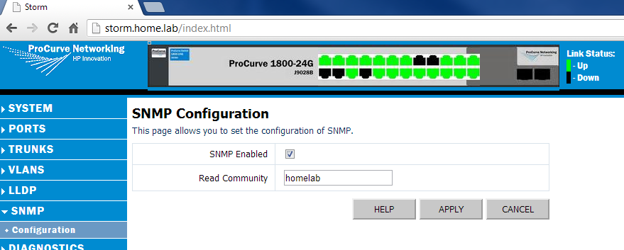
The last step is just to enable SNMP. This usually requires just enabling SNMP, setting a read community name (careful with read-write, as that can permit an SNMP device to make changes to your switch), and permitting the IP of the SNMP trapper in some cases. With HP, this is simply done by clicking on the SNMP menu, clicking SNMP Enabled, and setting the Read Community name (in our case we’ll call it homelab) as below:
And Voila! Switch is configured and now we can start building virtual machines!

